
(Note: I recently published a sort of expanded and updated version of this post. Some—but not all—of the information here has become obsolete in the newer versions of Cycles. However, some of the techniques explained here are still useful. You can find the new post on this link.)
For a while now, Blender has had the option of taking advantage of several UV projections on the same mesh. The different UV projections can be created in the UV Maps panel in the Object Data section of the Properties Editor (figure 1). In order to create a UV map, just click on the + sign in the UV Maps panel. Alternatively, you can select a mesh, go into Edit mode, select the desired polygons to UV map, press U to access the UV mapping floating menu, and choose a UV mapping method. With the second method, Blender creates a UV map by default.
 |
| Figure 1. Notice that there are two different UV maps for the same mesh. Figures 2 and 3 show what they look like. |
In order to create additional UV projections, just click again on the + button, and choose a UV mapping method by pressing U while in Edit mode. You can see what the different UV projections look like by opening the UV/Image Editor window. Figures 2 and 3 show the what the two UV maps in this example look like.
 |
| Figure 2. This UV projection corresponds to the Scratches UV map. |
 | |
|
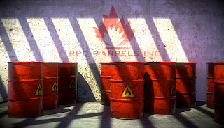
The reason why I explain all this is that, at the time of this writing, Cycles does not have the possibility of stopping the tiling of an image texture over a UV map. Blender Internal has a nice option that forces the texture to not tile. In Cycles, on the other hand, if you need to place decals over a mesh via a texture, you run into the problem that, if you are using more than one texture on your object, but use only one UV map, the decal won't look good at all—multiple copies of it will appear over the mesh, because of the tiling (see figure 4).
 |
| Figure 4. If you use the same UV map on a texture that appears everywhere on a mesh, you'll get a repeating pattern for the decal. |
The workaround is to use several UV maps, one for each texture. By using the two different UV projections as seen on figure 2 and 3, and applying a different image texture to each, we can control which polygons receive which texture. However, in order to do so, we need to use material nodes, specifically the Attribute node. The Attribute node can be found by switching to the Nodes window. Make sure you're in the Material Nodes section of the Nodes window.
In order to take advantage of the nodes, you first assign a material to your object in the Material pane. The default material will do for now. Then, you switch to the Node window and click on the ball icon to the far left (figure 5).
Keep adding nodes as needed, and connect them by dragging from the different input/output sockets as needed. The final setup for using two different UV maps on two different textures should look like the one in figure 7.
In order to take advantage of the nodes, you first assign a material to your object in the Material pane. The default material will do for now. Then, you switch to the Node window and click on the ball icon to the far left (figure 5).
 |
| Figure 5. Make sure that the ball icon is highlighted. This way, you'll be able to edit material nodes. |
In order to add a node, hover the cursor over the Nodes window, and press Shift + A. A floating menu appears which lets you add specific nodes. The Attributed node can be found under Input (figure 6). Your floating menu might look different than the one shown here because Cycles is still under development, and new nodes will most likely keep being added.
 |
| Figure 6. Press Shift + A to add a new node. Go to Input > Attribute to add the Attribute node. |
 |
| Figure 7. You need to type the exact name of the UV map that controls the placement of the specific texture on the mesh. Connect the blue output in the Attribute node with blue input in the Image Texture node. |
One final thing that needs to be done is to use a Mix node to combine the two different textures—each with its own UV mapping. Connect the yellow output of each image texture node into one of the two yellow input in the Mix node (figure 8). Additionally, you need to use a third image texture, usually a grayscale version of the sticker image, to block the pixels of one texture from the other. Essentially, this grayscale image texture acts as a mask. I created my own mask by converting the sticker image to grayscale in Photoshop (figure 9). You could also use nodes to do this, specifically by using the RGB to BW Convertor node. In this example, I also needed to invert the texture by using an Invert node. This grayscale image is then fed into the Fac socket in the Mix node.Make sure you select the correct UV mapping for this image as well—in this example it is the same UV map used by the sticker image (flammable_sticker).
|

| Figure 9. The masking texture. |
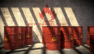
With the right UV map applied to each image texture, the decal looks fine this time (figure 10).
 |
| Figure 10. The decal appears like it should with the correct UV map applied. |
 |
| Blender internal plus compositing. |
 |
| Cycles plus compositing. |
thanks, a great tutorial, good to know we can have two UV maps.
ReplyDeleteThanks! When I have the chance, I'd like to update the tutorial to give a more detailed explanation to the mixing of the two textures through a MIx node controlled by a B&W image.
ReplyDeleteIt's good that blogs like this exist, as many starting modelers search information and sometimes help for their projects. Ty for the tutorial.
ReplyDeleteThanks for your kind comment and I'm glad you find it useful :)
ReplyDeleteI can't get it to work. I added the attribute node, and even tried to copy your complete node setup to get the answer. But I can't seem to get it work. Any ideas?
ReplyDeleteThanks. I didn't know how to do this in Cycles.
ReplyDeleteAny time :)
ReplyDeleteThanx a lot :) .this helped me
ReplyDeletethanks a lot, i searched for this so many times!
ReplyDeleteIt sounds very good. I having problems trying to exactly put an image using the UV editor. For a unknown reason, the image completely spreads on the mesh, a cube, for example, once rendered. The UV unwrap doens't seem to work as good as in Blender Render. I guess I have something missing, here in my mind. Im using Blender 2.64. I'll keep on trying. Great tutorial.
ReplyDeleteAl, thanks for your comment. I'd be more than happy to help if you're still having issues with the UV mapper. Just send me an email (listed on the left sidebar near the top, under "Contact me." Do you think a comprehensive UV mapping tutorial might be a good idea?
ReplyDeleteHi ,this is just what I've been looking for!
ReplyDeleteI have managed to create the two UV for the same object but I'm struggling to assign two images (one for each UV map) The same image appears even if I assign two in the materials section. Can you help and let me know what I'm doing wrong??
hi, I came to almost the same result as you are by converting from BI to Cycles. But still not solved a single problem: how to make that appeared black color at logo on the barrel?
ReplyDeleteHi Andreu,
ReplyDeleteI have a question, please: What is the role of the RENDER button at the end of the UV cell?
If I have 3 UVs and I clic on one of this button, nothing appens....I don't understand!
Spirou4D, that's an interesting question. When you are using an image texture (that is, non-procedural texture) for a material, and you don't specify which UV map you want to use for the texture, Blender uses the UV map that has the camera icon selected in the UV Maps sub-panel—that's the Render button you're talking about. You can try this test: create a basic Cycles material. Attach an Image Texture node for the Color. Create two different UV Maps. Now, if you go into Rendered preview in the 3D Viewport, and click on the camera icons alternatively, you'll see the two UV maps being used according to which camera icon is selected. I hope this makes sense.
ReplyDelete