A couple of years ago, I wrote a
small tutorial on how to apply one or more textures as decals to one single mesh in Cycles. The technique back then took advantage of using several UV maps fed through the Attribute node. Today, I am revisiting this topic because it is perfectly possible to apply one or more images to mesh in Cycles with total control over scale, rotation, position—and more importantly, tiling. Let's see how this is done.
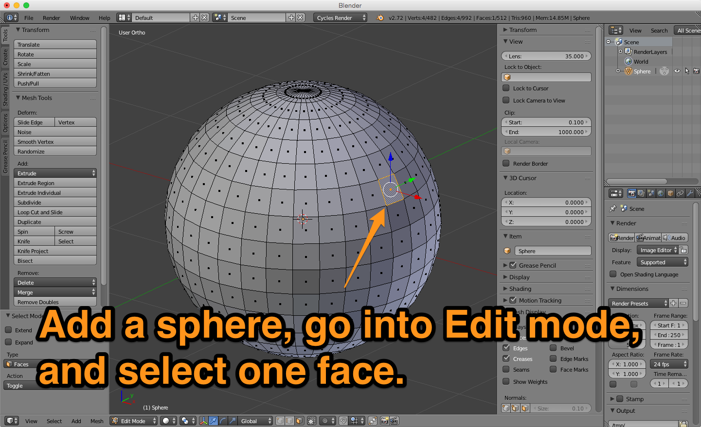
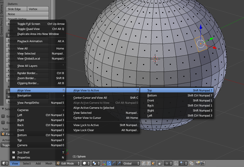
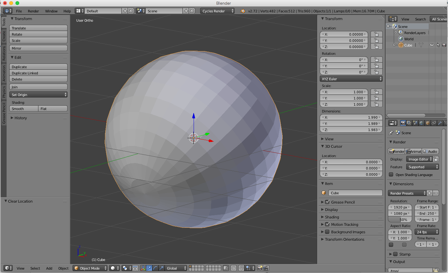
Open up a new Blender file, get rid of everything, and add a plane. Press 7 to switch to top view and Shift-C to center the view on the plane. I like to work on Orthogonal view, but that's me. Create a material for the plane. Split the window to have access to the Node Editor. In the 3D Viewport, switch to Rendered shading mode. Now, with the plane selected, go into Edit mode, select all, and press U to UV unwrap the plane with the option Project from View (bounds).
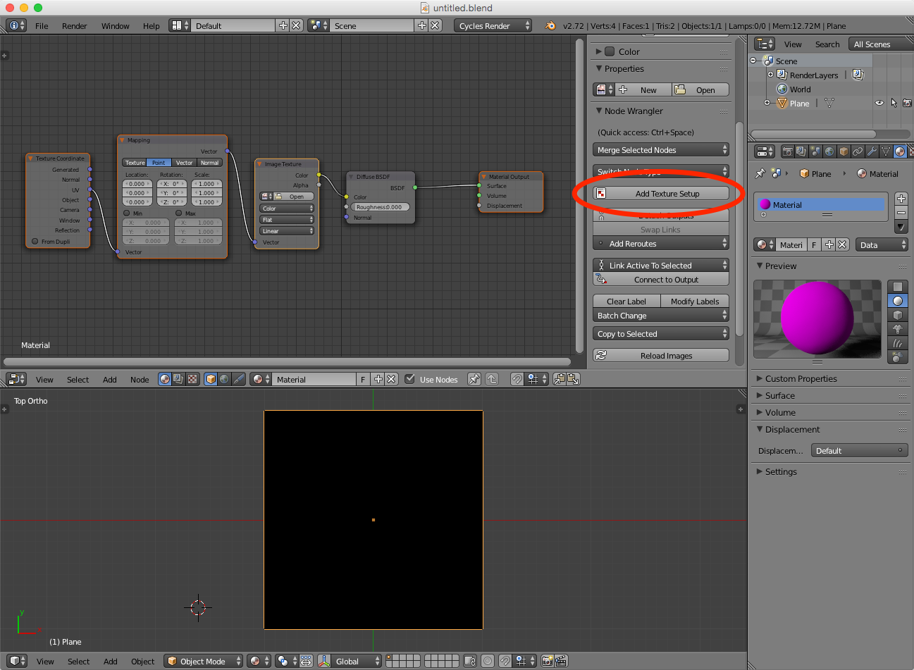
Now, make sure you have the Node Wrangler addon activated. In the Node Editor window's Properties panel, click on the Add Texture Setup button. This adds a Texture Coordinate, Mapping, and Image Texture nodes and connects them to the existing Diffuse node (Figure 1).
 |
| Figure 1 |
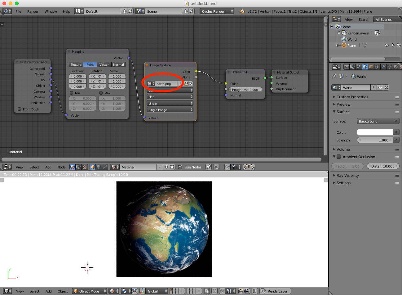
Now you need to choose an image texture in the Image Texture node. I am using a free image of an earth I found on
Pixabay. The image I used is a PNG with a transparent background (Figure 2).
 |
| Figure 2 |
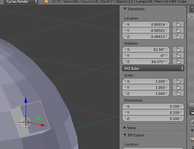
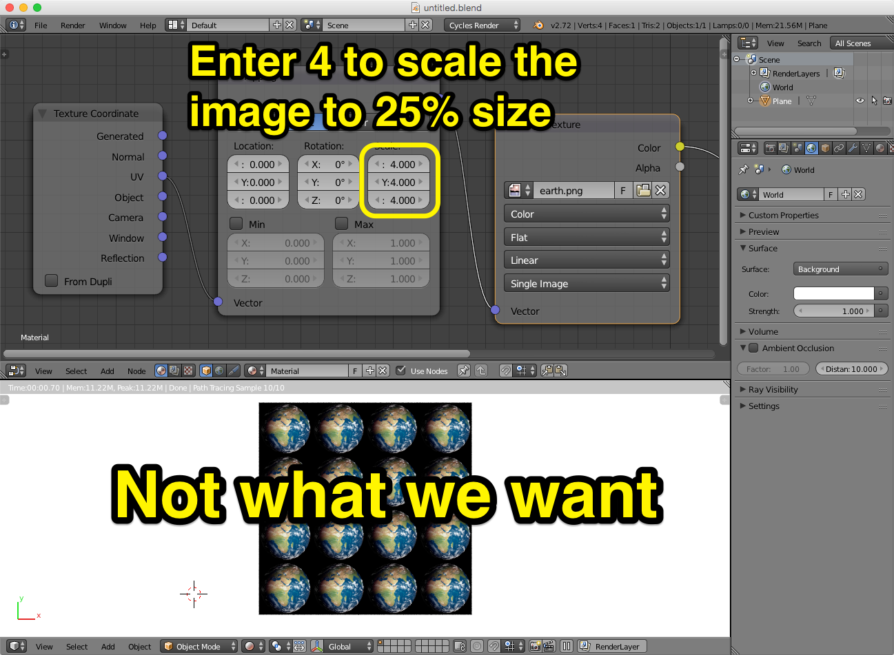
Now, I'd like to scale this image down to 25% and place one single instance of it—that is, without tiling it. However, when you change the scale in the Mapping node, the image becomes tiled! This is not what we want. Notice I am using the Point option in the Mapping node, which alters the projection itself, not the texture. To scale down the image to 25% size, you need to enter a 4 (Figure 3).
 |
| Figure 3 |
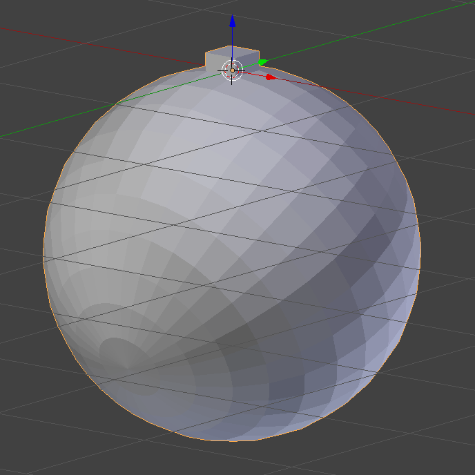
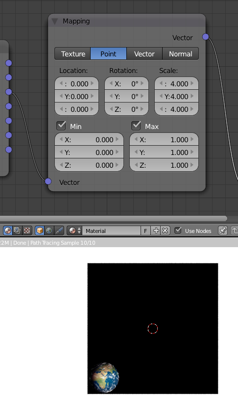
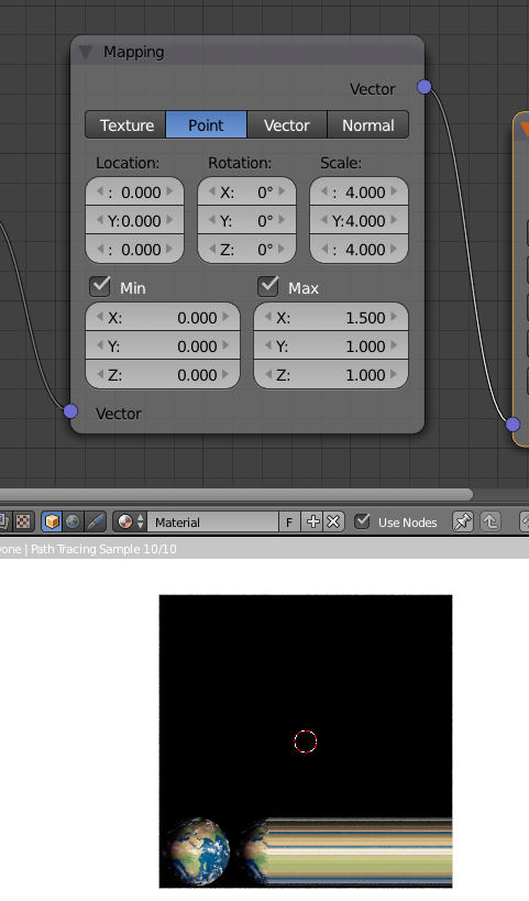
So, how do we stop the image from tiling? It took me a while to discover, but you do it by checking the Min and Max options, and entering the appropriate values. What does Min and Max mean? Min and Max control how a texture tiles over the XYZ axes, so the Min and Max value refer to dimension units in the texture coordinate. Check these two options and see what happens! The image texture stops tiling at the maximum coordinate value assigned under Max—which is one, so the tiling stops at 1 (Figure 4). If you enter non-integer values here, you'll get a bit of a tiling stretching over the remaining geometry in that axis. Blender simply extends the pixels at the texture's edge (Figure 5).
 |
| Figure 4 |
 |
| Figure 5 |
I'd like to scale the earth to 50% its original size, and place it in the center. There are several ways to do this with the mapping node. I find that using a 2 scale in Point mode, and changing the X and Y location to -0.5, as seen in Figure 6, works well enough.
 |
| Figure 6 |
OK, so we can stop an image texture from tiling over the whole UV projected mesh. This is actually great news for decal professionals in Blender. What about adding a second image texture to the same mesh
without using a second UV map? Piece of cake. Image 7 shows the noodle I am using. I am simply using a different Mapping node for the second image (the moon). For this example, I am mixing the two textures with the Add mode. Also, it is important to combine colors of different image textures before plugging the color info into a shader node. Combining color info at the shader level becomes more restrictive, because we lack certain mixing modes for shaders.
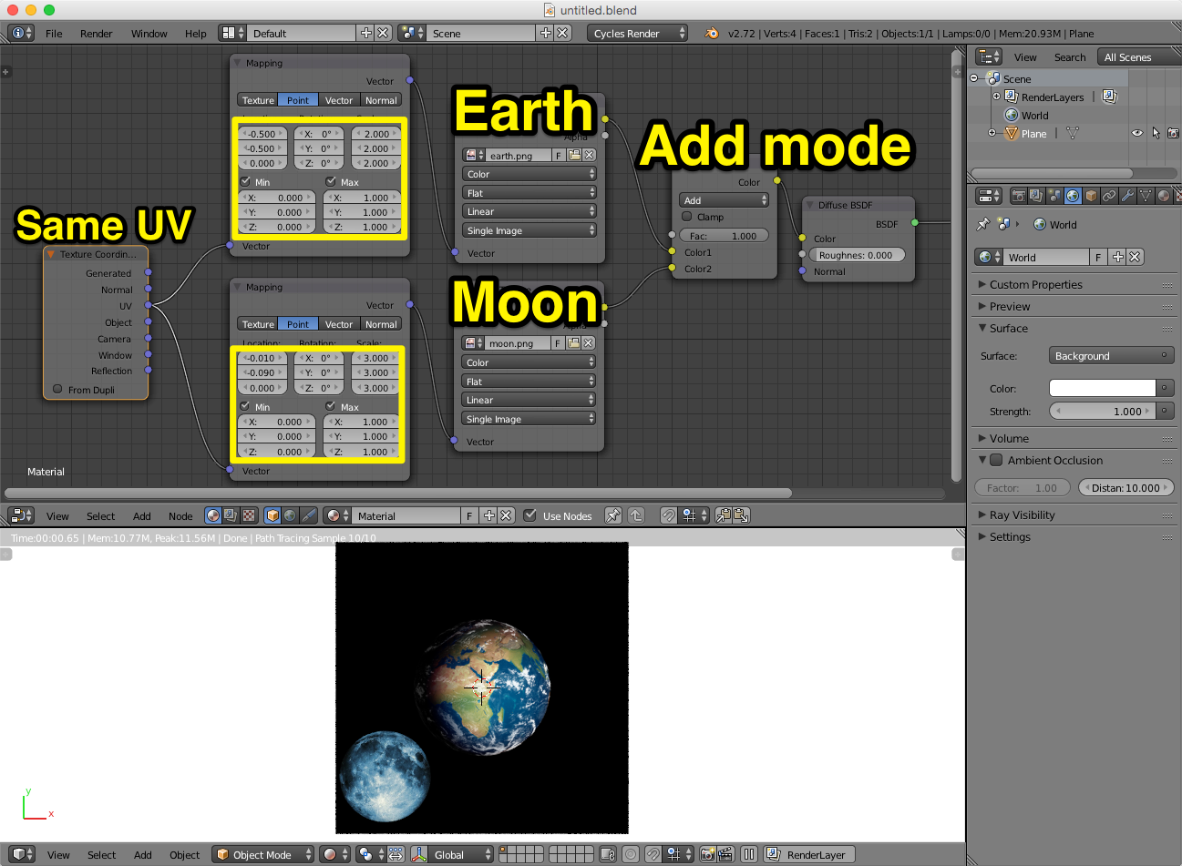 |
| Figure 7 |
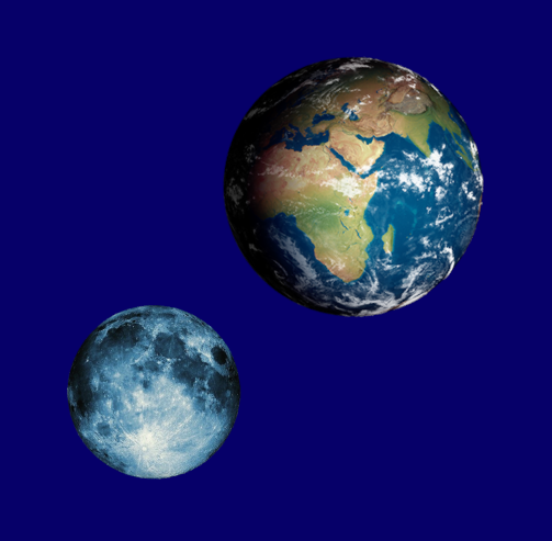
Let's take this one step further. I want the plane to be dark blue, and I want to place the earth and the moon on top of it as if they were bumper stickers. For this, I will use the alpha information from the texture images themselves, I will combine them into one grayscale image, and this will control the mix between two shaders—one with the earth and moon, the other, dark blue. Image 8 shows the final node setup.
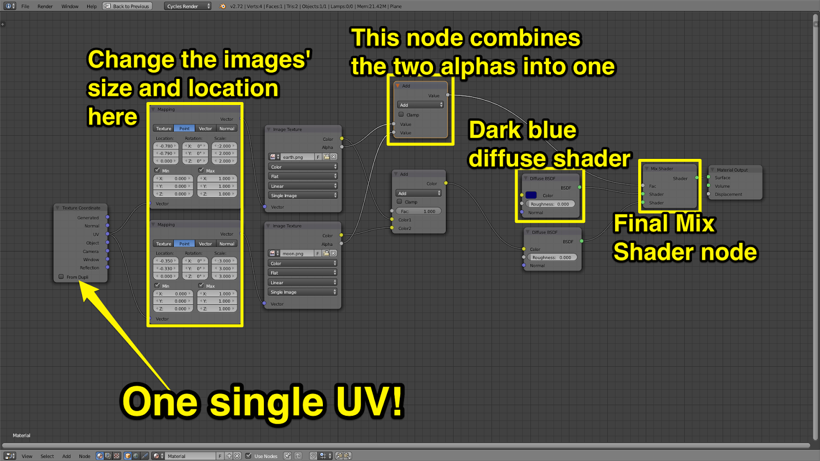 |
| Figure 8 |
 |
| Figure 9 |